Pfeiffer Vacuum are specialists in vacuum technology. They provide the highest quality testing in order to provide top class products. Here we learn about the importance of the pump down curves and the different materials that can affect them.
Displaying and interpreting processes in different vacuum ranges
Pump down curves are a popular control instrument when designing and operating a vacuum system. Thanks to them, any problems in the system can be derived and the correct pump performance can be assessed.
A pump down curve describes a time-dependent pressure drop in a vacuum system. In a graphical representation, the time is applied to the X-axis and the pressure to the Y-axis. For the known geometry of the vacuum chamber and pumps, a pump down curve can be calculated. Any deviations between the calculated and the measured pump down curve will often provide information about problems in the vacuum system. This also applies to the comparison of curves measured over long-term use with a reference curve.
Pump curves in in the low vacuum range: displaying connections, interpreting, and applying
A reference curve can be measured when the system runs properly and without any problems after startup. Under these conditions, the pressure drop is measured over time during pump down. The measurement can either be taken manually, using a system control, or using the software packages for pressure gauges provided by Pfeiffer Vacuum.
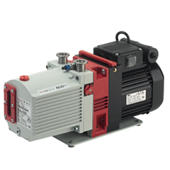
In the example in Figure 1, the calculated pump down curve of a 100-liter chamber is displayed. A Duo 65 rotary vane pump was used as a vacuum pump. This curve serves as the standard for comparison. In Figure 1, it is assumed that the pump is directly connected to the chamber.
In Figure 2, the effect of a flexible corrugated hose on the pump down behavior can be seen. It is used as a connection between the chamber and the pump. The tube has a length of 1000 mm and a diameter of 40 mm.
The connecting bellows have almost no effect on pump down time above a pressure of approximately 1 hPa. But if we want to further evacuate the chamber down to 0.01 hPa, the pump down process will take about 20% longer, solely due to the effect of the bellows. A solution for this is to shorten the connection piece or to increase the piping diameter.
Flow resistance depends linearly on the length, but in the third or fourth power on the diameter. If in doubt, the diameter should be increased as a corrective measure rather than shortening the connection. In this case, the comparison between the two curves shows the influence of the pipe and can help with designing the connection between the chamber and the pump.


