Expert failure analysis techniques deliver improved reliability
Sophisticated, modern turbomachinery relies on complex alloys and precision engineering to ensure reliable operation in demanding applications. However, changes in operating conditions and procedures can lead to equipment working outside its original design envelope. In the event of an unexpected failure, expert investigation and analysis can address design flaws and deliver lasting reliability.
Three of Sulzer’s leading engineers, Kirill Grebinnyk, Dr. Vamadevan Gowreesan and Ricardo Guerrero offer an insight into the complex and microscopic levels of detail that are required in the analysis of material failures in turbomachinery components.
There are cases when turbomachinery, such as steam turbines, axial and centrifugal compressors and hot gas expanders, may experience some form of mechanical failure during their operational lifetime. Performing failure analysis provides a comprehensive understanding of the cause and is essential for making the best decisions to mitigate future failure occurrences.
Establishing the framework
Within a wide range of industries, a large number of turbomachines are relied upon to deliver vital aspects of a manufacturing process. However, the process conditions and operating procedures can change quite significantly over time, and this in turn creates conditions when the equipment may temporarily or continuously operate beyond its original design specifications.
Together with components reaching the end of their service life, there is an increased risk of failures that may, at first glance, be unexpected. By instigating a detailed failure investigation and design review, it is possible to expose the underlying causes and establish corrective actions to address them.
Sulzer has established a general framework that contains all of the necessary steps to understand both the application and the causes of the failure. Following such framework makes it possible to draw a complete picture of the circumstances surrounding the failure, deliver a conclusion and determine the actions to mitigate similar failures in the future.
Material analysis
The visual inspection of a fracture surface and the surrounding components forms the basis of the initial analysis. Non-destructive testing (NDT) is used to examine the whole assembly as well as the area of the failure itself. In many cases, indications of a similar failure at an earlier stage may be discovered elsewhere in the component. Studying these areas and comparing them to the fracture site, can offer important insights to the initial cause.
The evaluation will then progress into opening up the crack for an analysis with stereo microscope, scanning electron microscope (SEM) or transmission electron microscope (TEM). The investigation looks for the primary mode (mechanism) of failure, the failure initiation site, material microstructure, any pre-existing defects from manufacturing process or service. Each failure mode has its own tell-tale signs and appearance of the fracture surface that can be referenced to the investigator’s previous experience as well as to the literature and scientific publications in the area of material sciences.
Materials analysis identifies the base material alloy used in the construction of the component and gives an indication to the mechanical properties of the material.
Mechanical testing
Hardness testing is the easiest way to estimate the mechanical properties of a material. Best practice is to test several locations around the failure zone as well as those in an unaffected area, which are used for comparison.
However, the hardness readings within the expected range may not necessarily indicate good condition of the material. In some cases, a few competing deterioration mechanisms may affect the parts with some of them causing hardening, while the others are resulting in softening.
If the failed samples are large enough and allow for mechanical testing specimens to be cut, the tensile and impact toughness testing are done to precisely determine the properties of the material. The main challenge is to make sure the specimens are extracted from the location which is representative enough for the failed area.
If a failure mechanism is suspected to be related to high temperature deterioration, a stress-rupture and creep testing may provide additional information about the material condition.
Microscopic examination
To determine the failure mechanism, it is critical to understand where and how the fracture initiated, how and for how long it propagated and where the final failure occurred. Microscopic examination can provide evidence of the presence, or absence, of material deterioration mechanisms, such as grain coarsening and dislocation, embrittlement as well as impurities present in the material.
For example, brittle failure occurs rapidly without any noticeable macroscopic plastic deformation. Depending on the nature of the brittle failure, the fracture surface may exhibit a chevron pattern or herringbone pattern. This pattern shows the direction of crack propagation and also points to the crack orientation. This pattern is particularly pronounced in plate-like parts such as impellers and discs.
Design assessment
A thorough understanding of the design and fabrication methods involved in creating the equipment is very important for a successful investigation. One of the main questions that the analysis needs to answer is if the failure was caused by a pre-existing design flaw, deterioration of material or if the original design was unsound or unintended for a particular operating condition.
The following aspects of a failed part design need to be studied and understood:
- Determine sources of loading – centrifugal force, thermal gradients, gas bending forces
- Determine the static (steady state) and cyclic (alternating) loads acting on equipment and its components
- Is the type and amount of load typical for the design or was there an abnormal loading event involved (such as overspeed, temperature excursion)?
Finite element analysis (FEA) and computational fluid dynamics (CFD) studies are usually performed to determine the stresses under design and off-design loading conditions. The level of detail to which the calculations or simulations extend is determined by the team conducting the analysis. Too many details in the numerical study make for a very expensive and time consuming simulation. On the other hand, over simplified models may neglect important loads and lead to incorrect conclusions.
Drawing conclusions
Ultimately, delivering the final analysis of the failure mode and the underlying causes is the most challenging part of the process. By following an established framework, the chances of a successful outcome are significantly improved. Determining the amount of evidence that is used to support the conclusions is an issue that can be debated for some considerable time.
Very often, this will be decided by considerations such as the importance of the equipment to the process, the financial losses incurred by the failure and the impact of the failure on the safety of personnel. As the importance of the safe and reliable operation of the equipment increases, so the amount of resources attributed to its failure investigation, redesign and repair will increase.
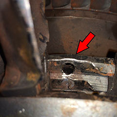
Example case study: Axial-flow expander locking blade failure
The locking pin for a blade in the third stage of an axial-flow hot gas expander rotor had failed. The failure analysis was undertaken by Sulzer to determine the basis for the design and establish the cause of the failure.
About Sulzer:
Sulzer is the leading worldwide, independent service provider for the repair and maintenance of rotating machines including turbomachinery, pumps and electro-mechanical equipment. With a global network of over 180 technically advanced manufacturing and test facilities, Sulzer offers a collaborative advantage that delivers high-quality, cost-effective, customized and turnkey solutions, providing its customers with the peace of mind to focus on their core operations.
Sulzer Rotating Equipment Services, a division of Sulzer, can accommodate all brands of rotating equipment including turbines, compressors, generators, motors and pumps. With an enviable track record, dedicated teams of on-site engineers provide best-in-class solutions to ensure that the most effective service is delivered.
Sulzer is dedicated to providing superior service solutions to a range of industries including power generation, oil and gas, hydrocarbon and chemical processing, water and air separation. Every solution is customized to suit the business needs of each application – whenever or wherever that may be.
With a long history of providing engineering service support, Sulzer is headquartered in Winterthur, Switzerland where it began in 1834. Today, with sales over US$ 3 billion and with approximately 14,000 employees, the Sulzer footprint spans across the globe. The core aim is to deliver a flexible and cost-effective service that optimizes customer operational efficiency and minimizes downtime.
For more information on Sulzer, visit www.sulzer.com