Offshore workers know the challenges of finding the right weather windows and suitable sea states. Often it’s a race against time in order to finish the operations within safe conditions. Or worse, you sail out and discover it was all for nothing, due to rough seas and you have to sail back to harbour. Read on to find out how real time forecasting was used during the TetraSpar Demonstrator project.
Operations offshore to construct and maintain the offshore wind farms are hugely affected by the weather conditions. Weather and waves are the major risk factors for offshore operations. Waves especially contribute to the downtime during projects as the work is only allowed in limited wave conditions for safety reasons. While wave measurements are often done from transformer platforms or turbines, it’s also very logical and often more convenient, to measure waves from a vessel.
As Radac is known for her reliable wave radars used in the offshore wind industry, we often get questions about our experiences on board of vessels. Many construction, pipelaying, and survey vessels have a Radac wave radar installed to be able to monitor the sea state during their operations. Real time wave data from the offshore wind farm is not always directly available to them. Or the measurement location is too far away from their operation location.
The captain of a survey vessel shared with us the following. ‘Very often, forecasted wave data differs from the actual wave data. In such cases, without wave radar we used to wait until the wave trends are confirmed or wait until the light comes up to check it ourselves. Thanks to Radac systems on-board our vessels, we are now able to check, wave-sea state data in real time, regardless the time of the day, and continue our operations which we would have previously missed due to the unknown.’
This is just one example of the feedback we get from the field. To give a more detailed view on the use of wave data at a vessel during operations, in this article we dive into the TetraSpar Demonstrator project (see box). Bastian Lykke Bojko, senior consultant at Blue Power Partners, was on board during the towing campaign and told us all about the project.
The TetraSpar project
The floating structure of the TetraSpar had to be towed from Grenaa Harbour all the way up to the Marine Energy Test Centre (Metcentre) near Stavanger in Norway, approximately 360 nautical miles. Several critical steps on the route were identified for specific operations.
First they took the structure out of Grenaa harbour. Due to the water depth the 166m high structure sailed out with the top part floating and the keel pulled in. As the keel provides stability, the keel needs to be lowered as soon as the water depth allows. At 6 nautical miles out, at 14m water depth, they were able to lower the keel by 4m. The significant wave height for this operation was set at a limit of 0.5m. In other words: completely flat.
Then they had to tow her further out to be able to lower the keel completely, 60m and fill the keel with water. This was done near Skagen, the most northern part of Denmark. The limit was 0.8m here. Now the floating structure is ready to be towed up to the installation side where anchors are preplaced on the sea bed to connect to the structure. With the keel completely lowered the maximum wave height was 2m.
For each step there were wave limitations for structure operability and stability. That’s where the Radac wave radar comes in. They had to make sure that the forecast was trustworthy and the critical operations could take place. Is the actual wave as what was forecast? Does it show the same trend as forecasted? During the whole towing it’s a constant flow of checking: forecast says…, wave radar says… and then a go/no go decision follows. Over and over again.
The real time waves were monitored by a Radac system that is installed to the railing on the side of the towing vessel, close to the bridge. This motion compensated wave radar is in a single unit system which is easy to install with a rail mounting frame. The radar itself facilitates data acquisition, data processing, data presentation and remote service functionalities as well as internal data storage. Data will be internally stored on the device and distributed over the vessels network. Any device connected to the private network of the vessel can access the web-based user interface.
The unit has to have free sight to the water surface and measures the distance to the water 10 times per second with centimeter precision. Due to the long term stable zero reference of the fmcw (frequency modulated consistent wave) radar, calibration is not needed. The distances measured are compensated for the heaving, pitching and rolling motion of the radar. Thanks to a highly sensitive motion sensor which is incorporated into the radar unit. The Radac WaveGuide Onboard measures the waves the ship actually has to endure.
It truly is a plug and play system, which makes it very suitable for these kinds of projects where the vessel is hired and comes only a few days before the start of the project. ‘The accuracy always is difficult to say as it can only be held to what I observed. But I’m happy to say that it’s very accurate in the way it measures the waves. Leaving the vessel movements out, the net readings so to say, worked very well.’ says Bastian.
Execution of this project required stable conditions at sea, therefore the limit of the significant wave height (Hs) was set to 0.5m for the very first stage of the keel lowering event. If forecasted wave data was the only source and it was suggesting anything higher than the limited wave height, this could cause a significant down time or risking equipment and operation.
After this first stage of lowering, second stage was set to lower the keel by 60m and the acceptable wave height was restricted to 0.8m. The operation of keel lowering and ballasting itself normally would take a couple of hours, but as it is a demonstrator project all was done at slow pace. The operations are new to everyone and lessons need to be learned. In this case the ROVs needed to check the process as well. During ballasting the ROVs needed to sail around and open the valves. The whole process took about one and a half days.
And after full keel lowering and ballasting the wave limit was 2m during sailing. Now the structure is in the final condition of installation, there is the option of the so-called survival mode of the turbine. She can sit in approximately 13m waves in this mode when anchored. A 4.5m wave height was determined as a survival condition, meaning they could remain in position with the tugs and structure, but not make any speed.
During the last part of the journey they temporarily experienced 3m waves. In this case lowering down the towing speed was enough to encounter the waves. There would have been the option to sail to shelter as well. But this would mean extra risks because of changing the route, crossing maritime channels and adding extra towing days. Sit and wait in the survival mode was the safer option and well within the limits.
As said before, one of the main functions of the wave radar is to confirm or disagree with the forecasts in order to make the go-nogo decisions by the crew. On the other hand, the wave data are crucial for the post processing and analyses of the project.
During all stages of the campaign, the wave data are correlated with the structure behavior and the towing speeds. And yes, you can save the forecast, but that’s a forecast. To correlate the data the real time measured waves are of better use. How did the waves effect the conditions during towing and the tension in the towing lines? And how does the data correlate with the engineering aspects like forces on the structure and the tensions on the keel lines? You can’t do this based on the forecast data. You want to test it from all different angles to be able to finetune the process and make it ready for multiple installations.
In this case there is an extra advantage as another Radac wave radar was pre-installed at the TetraSpar floating turbine. The directional system with motion compensation stored all wave data during the campaign and will be very useful for the post processing. Although the real job of this Radac system, is to monitor the sea state during the life time of the TetraSpar floating turbine when she is in function. As there is still plenty to learn and discover. Hopefully she won’t encounter too many 13m waves. We’ll have to wait and see!
The TetraSpar Demonstrator project
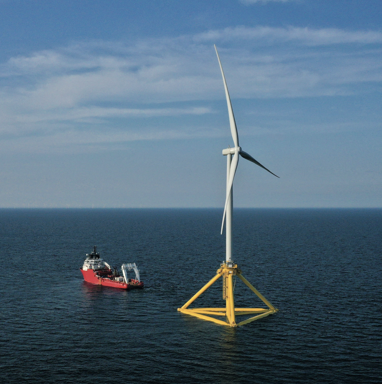
The TetraSpar Demonstration Project is the world’s first full-scale demonstration of an industrialized offshore foundation. The project is carried out in a partnership between Shell, RWE, TEPCO Renewable Power, and Stiesdal Offshore Technologies.
The TetraSpar foundation is a tetrahedral structure assembled from tubular steel components. It is expected to offer important competitive advantages with its potential for lean manufacturing, lean assembly and installation processes, and low material costs.
The foundation and keel were assembled using no welding at the Port of Grenaa in Denmark. A 3.6 MW wind turbine from Siemens Gamesa Renewable Energy was mounted on the foundation at quayside using a landbased crane after the launch of the structure in the harbor basin.
In July 2021 the combined structure was towed to the test site at the Marine Energy Test Centre (METCentre), off Karmøy near Stavanger in Norway. Here, the TetraSpar Demonstrator will be commissioned at a water depth of 200m.

