Words: Dr.-Ing. Joachim Jaus, Black Photon Instruments GmbH
Solar irradiance measurements provide valuable information to select a site for the construction of a solar power plant, to calculate the efficiency of the plant operation, or to determine possibilities for improvements of the power plant setup. But only precise measurements can do the job well. Dr Jaus explores how to circumnavigate the potential pitfalls.
Accurate data of solar irradiation is needed in many stages of a solar power plant: it starts in the early life cycle of a solar power plant where accurate solar irradiance measurements enable the project developer to select the most suitable site. Normally, this step of site measurement is preceded by a site pre-selection based on multiyear satellite data analysis. For a bigger power plant with 50 MW peak, each per cent in measurement error can mean more than a million US Dollar in misjudgment of the project’s total revenue.
After the power plant has been installed and connected to the grid, one of the most interesting numbers for both the power plant installation company, and the future operator is how much power the new plant produces. To derive this number, both the plant output power as well as the solar irradiation is measured with the highest precision. Again in this stage, each percent in measurement error is translated to millions of US Dollars in gained or lost turnover for the affected parties.
During the operational phase of the power plant, accurate solar irradiation data is viable to assure a good operation of the power plant. Concentrating Solar Thermal Power (CSP) plants based on steam operated turbines place the highest importance to accurate solar radiation measurements, as parameters such as pressure settings and flow rates are adjusted depending on the current solar irradiation. To cover transitional effects of clouds passing through, a standard 50 MW CSP plant will typically be equipped with five highest-quality solar irradiation measurement stations, one located in the plant center and one in each edge of the plant area.
In photovoltaic (PV) power plants, especially in those small and medium in size, a single PV cell has been determined to provide enough accuracy for irradiation measurements. With increased demands regarding the accuracy of PV power plant monitoring, more and larger PV power plants also integrate the most precise means of solar measurements available today.
Measurement of solar irradiation data in practice
Solar irradiance means the solar flux incident on a surface, measured normally in W/m2. The integral of solar irradiance over time gives the solar irradiation or insolation, measured e.g. in W/(m2day). Therefore, these two words are often used in the same context, irradiance giving a focus on the current measurement and irradiance on the sum over time. The measurement of solar irradiance/irradiation comprises normally four different types of radiation:
1.Direct Normal Irradiance (DNI), which comprises sunlight coming directly from the sun as well as from an area around the sun with a diameter of approximately 10 times that of the sun. The sun appears from the earth as a disc (‘sundisc’) with a half angle of 0.25∞, and the DNI represents all radiation coming from a half angle of 2.5∞ around the center of the sun. The DNI is always measured with a surface oriented perpendicularly to the sun (‘Normal’), so a DNI instrument needs to be tracked to follow the sun’s movement (or as we would say having Galileo in mind: to compensate for the rotation of the earth).
2.Diffuse Horizontal Irradiance (DHI, or ‘diffuse’), which comprises all solar radiation on a horizontal plane that comes from any part of the ski except that portion that comes directly from the sun and is counted towards DNI. The DHI therefore represents all the indirect light. It is the result of the direct sunrays being scattered in the sky on water vapor molecules, on dust particles, or on any other molecule or particle that is present in the earth’s atmosphere and interacts with radiation. It also contains the portion of the sunlight that is reflected from the ground and then reflected back towards the ground, e.g. by a cloud.
3.Global Horizontal Irradiance (GHI, or ‘global’), the total solar radiation on a horizontal plane, with no distinction weather it comes from the sundisc area or from some other point on the sky’s hemisphere. It is therefore the sum of the DHI and the DNI, whereby the DNI must be corrected for the cosine of the incidence angle to address the fact that the DNI is measured on a plane oriented towards the sun whereas GHI is measured on a horizontal plane.
4. In-plane irradiance (or tilted irradiance) represents the total solar radiation that hits a solar module that is not installed horizontally, but at a certain angle to the ground. The in-plane irradiance therefore accounts for parts of the DNI, the DHI, the GHI and also for some irradiance that is reflected towards the modules.
Depending on the technology of a solar power plant, the DNI, diffuse, global and the in-plane irradiance have a different level of importance. For example Point-focused concentrating PV power plants can use only DNI, whereas for standard flat plate PV panels the in-plane irradiance determines the power output. However, even for these ‘simple’ PV power plants, also DNI and GHI are important because irradiation forecasts are normally given in these two categories, as the in-plane irradiation always contains power plant specific elements such as module tilt angle and ground reflectance (‘Albedo’). Therefore, a precise on-site DNI and GHI measurement can largely increase the precision of the models used to predict the power plant output by correlating the satellite based irradiance data (DNI, diffuse, global) with ground based measurements of global, diffuse and DNI and by validation of the models used to calculate in-plane irradiance from these values.
The usual setup to measure the four components consists of three to four solar irradiance sensors:
1.A pyrheliometer installed on a sun tracker rotating in the azimuth and elevation axis measures the DNI
2.A horizontally installed pyranometers measures the global irradiance
3.A shading device is mounted on the sun-tracker which moves a shading ball such that it always shades a second pyranometer mounted on the azimuth axis. This measures the diffuse irradiance.
4.For tilted-mounted modules third pyranometer is mounted with the same tilt angle as the solar modules to measure directly the in-plane irradiance.
1.1 Accuracy limits of modern instruments
Some openly available documents provide a great help in selecting, setting up and operating solar irradiance measurement equipment, such as the ‘Best Practices Handbook for the Collection and Use of Solar Resource Data’ from Tom Stoffel et al / NREL and the WMO/CIMO ‘Guide to Meteorological Onstruments and Methods of Observation’.
These documents also provide a classification of instrument accuracies. The manufacturers of solar irradiation instruments give references in their data sheets to these classes. With the best available pyrheliometers today (fulfilling the criteria of ‘first class’ in ISO 9060 and ‘good quality’ in the WMO definition) measurement uncertainty for the irradiation measurement of a 1h average of better than 1.5 % are possible. With the best pyranometers available (fulfilling the ‘secondary standard’ in ISO 9060 and ‘high quality’ criteria in the WMO definition), a measurement uncertainty of hourly data of 3 % is possible for GHI measurements. Other possibilities to measure DNI, diffuse and global are rotating shadowband instruments and instruments with multiple sensor heads and an irregularly shaped shadow mask. These instruments have higher uncertainties than the standard pyranometer/ pyrheliometer combination, but the exact level of uncertainty is currently subject of several studies. An extensive intercomparison has been performed by the Meteo Suisse station in Payerne within the COST.WIRE project with results available probably in Q4/2014.
When studying the classification and the datasheets of modern instruments more closely, it becomes apparent that DNI can be measured more accurately than global or diffuse. The reason for this are manifold, including negative effects of a glassdome and detector reflectance on the cosine response of a sensor, which only affect pyranometers that need to capture radiation from the entire hemisphere instead of only 2.5∞ as is the case in pyrheliometers.
Global irradiance measurements today are the most common measurements due to their importance for standard PV modules. Due to the higher accuracy of the DNI measuring pyrheliometers compared to standard global measurements with pyranometers, a popular choice to achieve high quality global measurements is to determine the global irradiance by measuring DNI and diffuse irradiance, and calculating the global based these two. The accuracy of diffuse component is also quite low, but in sunny locations it accounts for only a fraction of the total irradiance, so the errors in the diffuse measurement don’t affect the overall global irradiance result too much. In such a setup, the global irradiance is measured additionally directly with a pyranometer, with the results being used as a control value to detect large errors in the global irradiance derived from the DNI/diffuse calculation.
Challenges in measuring solar irradiance
The basic challenge of a high accuracy measurement of solar radiation becomes apparent by a comparison of the outdoor environment and the kind of environment in which high accuracy measurements are normally done: Calibration labs. A calibration room normally is a rather dry room, has a regulated temperature, and the level of dust and dirt is kept to a minimum. The real environment of solar radiation sensors has none of these comfortable properties. To the contrary, there are thunderstorms, desert winds, ice and snow, and what these natural phenomena can’t accomplish is done by little birds and spiders. To maintain high measurement accuracy in these conditions is a real challenge.
One of the most important tools to overcome the challenge is a very regular, normally daily cleaning schedule of the sensor’s detection surface. If the cleaning is furthermore accomplished by trained personal, no scratches on the glass surface are left behind, no traces of the wiping deteriorate the measurement, and the cleaning is well documented in a cleaning journal, accurate and reliable measurement can be taken. If any one of these factors fails, an unreliable and inaccurate reading will be the consequence.
If dirt and dust particles settle on a solar sensor, it affects its measurement capability. However, it depends a lot on the type of sensor how much it is affected by dust particles. Measurement instruments for DNI measurements (pyrheliometers) are much more affected than those for GHI or DHI measurements.
A dust particle scattering the radiation of a pyranometer for GHI measurements will have no big effect for most locations on the glass dome and for most scattering angles: the scattered radiation still reaches the detector surface. In contrast to that, at the pyrheliometer even a small scattering angle will result in the rays being deflected enough to no longer reach the detector surface. This explains why DNI measurements are particularly susceptible to soiling.
The soiling rate per day can be quite high, especially in dry and sunny locations. In a recent study performed by the DLR institute, an average 0.3 % to 1.6 % daily signal reduction for DNI measurement equipment was found in measurement campaigns at three different sites [1] (Wolfertstetter 2013). This explains why cleaning has such a high importance.
Measures to reduce cleaning and maintenance efforts
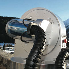
We designed the Sunscanner SC1 to implement measures to increase the accuracy and reliability of solar irradiance measurements. Due to the fact that DNI measurements with pyrheliometers are the most sensible to dirt, we focused the approaches on the measurements with pyrheliometers. The first of these measures is to ‘park’ the pyrheliometer during times were no measurements are performed in a kind of parking dock (see image).
The pyrheliometer can be put to its parking position at any time no measurement is needed, e.g. at night, but also during periods were there is no measurable direct sunlight. If measurements are only taken in intervals of several minutes, the instrument can also be parked during the measurements. Considering the time-constants of modern pyrheliometers of only a few seconds and the fast movement of the sunscanners elevation axis from park to measurement position in less than two seconds, this can be even done for one-minute measurement intervals.
Integrated into the parking dock there is a sensor cleaning system based on pressurized clean air (BPI.blast) (see image).
The pressurized air, which is generated on-site in the sunscanner’s cabinet, blows away any dust and dirt from the entry window of the pyrheliometer.
With the two systems BPI.park and BPI.blast the time between cleaning can be increased by about a factor of 2-6, depending on the location and type of dust prevailing at the site.
The beauty of this system is that no additional motor drives are needed to move the sensor into the parking position, instead the elevation drive is used to accomplish the motion. The pressurized clean air is generated at the site of measurement in the cabinet using a easy to clean 3-stage particle filter.
Measures to increase accuracy & reliability
The sunscanner provides a second elevation axis, where a reference pyrheliometer can be installed. This reference instrument can remain in its safe parking position for 99% of the time. Only once a day (or more, depending on the calibration strategy), the instrument is moved into its working position. After some settling time, the readings of the calibration and the working instrument are compared. This enables it to fundamentally increase the accuracy and reliability as it allows to:
Compensate for a soiling level. If the signal of the working instrument is dropping continuously compared to the reference, this can be attributed to soiling and compensated with a factor that is calculated from the ratio of working to reference instrument reading.
Check the working instrument for ‘too much soiling’: The difference between the working and the reference instrument gives a good representation of the amount of soiling. If a certain threshold level is reached (e.g. 3 % soiling), a service and cleaning mission can be scheduled.
Check both readings for consistency: If they differ by a significant amount, e.g. by more than 10%, something has gone fundamentally wrong. This will happen sometimes even in the best measurement setup and can have as ordinary reasons as bird droppings or more complex reasons in the data acquisition electronics or tracker control. The availability of a second sensor largely increases the probability to detect such a fatal error in the collected data and allows immediate action to be taken.
To achieve the best accuracy possible today, the Sunscanner SC1 also offers the possibility to implement an active cavity radiometer (ACR) in the setup. ACRs such as the PMO6-cc developed by the World Radiation Center in Davos, Switzerland, offers absolute accuracy better than 0.2 %. This instrument can be operated continuously outdoors with the Sunscanner SC1 using the BPI.PMOsafe technology (see image).
This technology provides all the means to keep a ACR in a good condition while operated outdoors, including a clean air supply, heating facilities, temperature and humidity control, a second protective cover around the instrument, as well as wind and rain detection so the instrument can be turned into its parking position as soon as adverse conditions are detected.
www.black-photon.de